


where dI(ω) is a sinusoidal perturbation of the photocurrent induced by a sinusoidal modulation of the light flow, dΦ(ω), around the working point (Vo, Io, Φo), with dΦ(ω)<< Φo. This technique is known as IMPS (Intensity Modulated Photocurrent Spectroscopy). The limit for a zero frequency of the transfer function η(ω) is the quantum yield, i.e. the number of electrons (or holes) produced for each incident photon.
Figure 1 : Simplified setup for the measure of the electro-optical impedance
Figure 1 shows an example of an experimental setup for the measure of η(ω). The light source is a LED or a xenon lamp. One can also use a laser coupled with an acoustic-optical modulator. The electro-optical impedance gives access to various processes giving birth to the photocurrent, i.e. charge transfer, recombinations, and charge trapping in surface states or in the bulk. The frequency study, typically between 10-2 and 105 Hz, provides information on the kinetics of these mechanisms.
Figure 2 shows the IMPS response of a photoelectrochemical cell based on a TiO2 nanostructured electrode sensitized by a dye (N3) in contact with an electrolyte containing the I2/I- redox couple. IMPS diagrams were recorded at different potentials between the short-circuit (V = 0) and the open circuit (V = - 800 mV). The frequency analysis gives an access to the variations of the rate constants of the charge recombination and trapping processes as a function of the potential, or yet to the effective diffusion coefficient of electrons in the nanocristalline network of the DSSC (Dye Sensitized Solar Cell).
Figure 2 : IMPS response at different potentials for a TiO2 based photoelectrochemical cell of the DSSC type photosensitised by a dye.
Another electro-optical transfer function was developed in our laboratory and adapted to the case of DSSCs. It is based on the excitation of the photoelectrochemical system using a composite signal involving two frequencies allowing the measure of the frequency dependance of the first derivative against the potential of an interfacial capacitance C, a characteristic of the studied system. The capacitance C is measured at the pulsation ω1 and its derivative ΔCω1(ω2)/ΔV at the pulsation ω2, with ω2 << ω1. The experimental setup is illustrated on Figure 3.
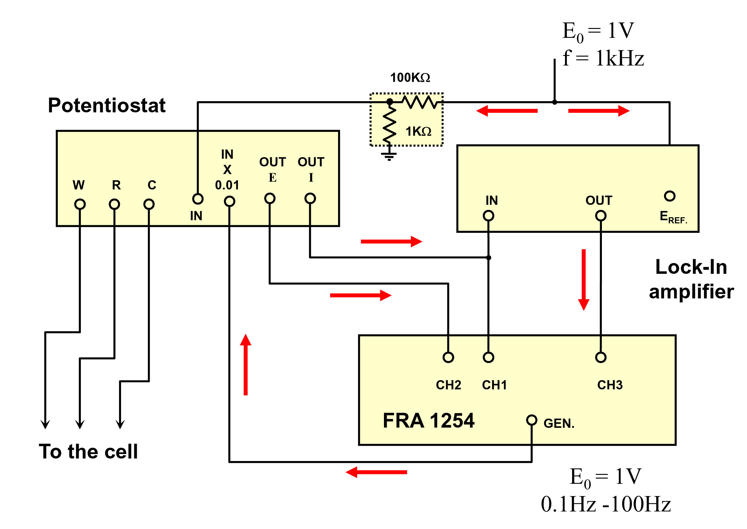
Figure 3 : Setup for the measure of the transfer function ΔCω1(ω2)/ΔV.
An example of a diagram obtained on a DSSC under illumination and fitted with a model is given on Figure 4. The interpretation relies on the same basis than IMPS. One obtains moreover an estimation of the contact area of the TiO2 network on the SnO2 substrate.

Figure 4 : Example of a ΔCω1(ω)/ΔV diagram measured on a DSSC.